Comparison between magnetic flap level gauge and magnetic float ball level gauge
The magnetic float of the high-temperature magnetic flap level gauge has degaussing during use, and demagnetization causes the magnetic flap level gauge to fail. High-temperature magnetic flap level gauges (especially high-temperature and high-pressure magnetic flap level gauges) generally use temperatures in excess of 180 degrees Celsius, and their installation is detachable with certain risks.
The magnetic flipper level gauge degaussing phenomenon can be divided into the following aspects:
A. From the design point of view, the appropriate hard magnetic material should be selected. For example, a magnetic material having a Curie temperature higher than 20% of the use temperature and ensuring that the residual magnetization exceeds a critical value after five years is selected.
B. From the perspective of production, the following points should be noted when processing magnetic floats:
1, cooling (argon arc welding) need to take cooling measures to avoid the temperature of the magnetic material of the magnetic float exceeds the Curie temperature of the magnetic material.
2. The magnetic float is filled with an inert gas (such as argon);
C. From the perspective of use, the user has to do the following:
1. When ordering, select the appropriate model and reach the nominal temperature of the magnetic flap level gauge.
2. In use, always observe the use of the level gauge (can be used normally), and also record the actual temperature of the medium (I have seen such a situation, the actual use temperature tends to be higher than the temperature on the parameter list, Those who design the parameter list may have overlooked certain factors).
The magnetic float ball level gauge is a commonly used instrument for measuring liquid level. It has the advantages of simple structure, convenient use, stable performance, long service life, easy installation and maintenance, and is widely used in petroleum processing, food processing, chemical industry and water. Level measurement, control and monitoring in the fields of treatment, pharmaceutical, power, paper, metallurgy, shipbuilding and boilers. However, during the detection process, due to the influence of interference factors, the following faults will occur in the magnetic float level gauge, which will affect the accuracy of the measurement results. Therefore, we will understand the fault of the magnetic float level gauge:
1. After the liquid level meter is used for a period of time, it is difficult to float and the float is not sensitive. This is basically due to the presence of iron filings or other contaminants on the magnetic float. The medium can be drained first, and then the float can be removed to eliminate the iron filings or other contaminants on the magnetic float.
2. Occasionally, during the on-site adjustment, it is found that the float is not sensitive enough. This is mostly caused by the improper installation of the level gauge device. At this time, it should be noted whether the center of the upper and lower flanges can be in a line and can be perpendicular to the degree. Generally speaking, the angle with the degree surface is not less than 87 degrees. If the deflection is large, it may affect the smooth movement of the float.
3. Select the intrinsically safe liquid level timing, especially pay attention to whether the impedance of the liquid level meter and the safety gate can match.
4. The magnetic float level gauge is adjusted normally. After the application, the float is found to be in a certain position for a period of “sucking†phenomenon. This is mainly caused when the level gauge passes through the steel platform device and is spaced too close to the steel plate. Therefore, the requirements for passing through the steel platform device pay special attention to the distance between the pipe wall of the liquid level gauge and the cutting edge of the platform.
5. During the operation of the level gauge, if the output signal generates frequent disturbances or interference pulses, it is necessary to check whether the signal cable shielding layer is firmly grounded, and whether the working connection is a resistor can satisfy the request.
6. When the liquid level meter is used on site, it is necessary to pay special attention to open the upper gate valve first and then open the lower gate valve. This is because the bottom of the connecting pipe of the liquid level gauge is equipped with a thrust spring for maintaining the float. Otherwise, the large differential pressure may crush the float and cause the liquid level gauge to be unusable.
7. If the closed glass tube used for on-site instructions is broken due to transportation or other reasons, the domestic glass tube can be replaced. But priority can be vacuumed. Also pay attention to whether the glass tube can be vertical, so as not to affect the indication of the indicator.
8. Pay special attention when using the magnetic float level gauge. Never use a strong magnet to pull the float on the outside of the connecting tube to stop the inspection. Otherwise, the magnetic float will be magnetized and the polarity will be changed, which will weaken the magnetic properties of the float, making it difficult to normal. jobs.
HDPE Water Supply Pipes
Hdpe Water Supply Pipes Appearance, standard and Application
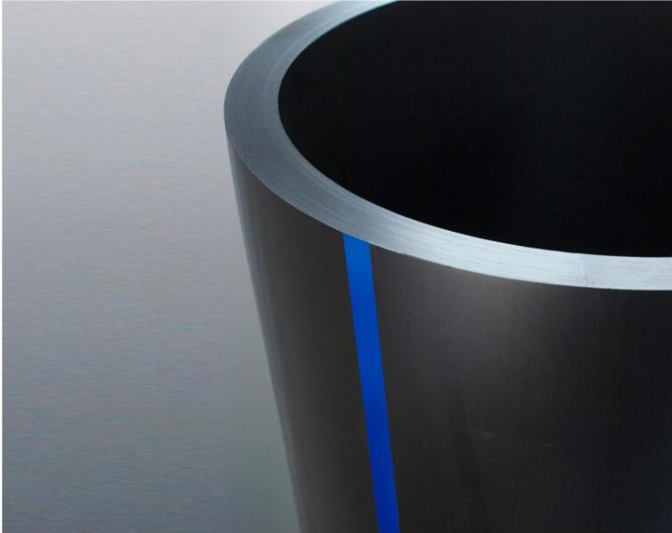
Black pipe body with blue belt. Implementation of GB/13663-200 《water supply HDPE pipe》;Drinking water pipe health performance in line with GB / T17219 requirements. The production have PE80 and PE100 two kinds of raw martials , generally used for pressure water transport. the products are widely preferred in the Urban water supply, municipal engineering, mining factory construction, fire protection, small town construction and civilized ecological village construction projects.
HDPE Water supply pipes Specification
PE100
1. OD 20mm(PN1.6)
2. OD 25mm(PN1.6)
3. OD 32mm(PN1.0.PN1.25.PN1.6)
4. OD 40mm(PN0.8.PN1.0.PN1.25.PN1.6)
5. OD 50mm(PN0.6.PN0.8.PN1.0.PN1.25.PN1.6)
6. OD 63mm(PN0.6.PN0.8.PN1.0.PN1.25.PN1.6)
7. OD 75mm(PN0.6.PN0.8.PN1.0.PN1.25.PN1.6)
8. OD 90mm(PN0.6.PN0.8.PN1.0.PN1.25.PN1.6)
9. OD 110mm(PN0.6.PN0.8.PN1.0.PN1.25.PN1.6)
10. OD 125mm(PN0.6.PN0.8.PN1.0.PN1.25.PN1.6)
11. OD 140mm(PN0.6.PN0.8.PN1.0.PN1.25.PN1.6)
12. OD 160mm(PN0.6.PN0.8.PN1.0.PN1.25.PN1.6)
13. OD 180mm(PN0.6.PN0.8.PN1.0.PN1.25.PN1.6)
14. OD 200mm(PN0.6.PN0.8.PN1.0.PN1.25.PN1.6)
15. OD 225mm(PN0.6.PN0.8.PN1.0.PN1.25.PN1.6)
16ËŽ OD 250mm(PN0.6.PN0.8.PN1.0.PN1.25.PN1.6)
17ËŽ OD 280mm(PN0.6.PN0.8.PN1.0.PN1.25.PN1.6)
18ËŽ OD 315mm(PN0.6.PN0.8.PN1.0.PN1.25.PN1.6)
19ËŽ OD 355mm(PN0.6.PN0.8.PN1.0.PN1.25.PN1.6)
20ËŽ OD 400mm(PN0.6.PN0.8.PN1.0.PN1.25.PN1.6)
21ËŽ OD 450mm(PN0.6.PN0.8.PN1.0.PN1.25.PN1.6)
22ËŽ OD 500mm(PN0.6.PN0.8.PN1.0.PN1.25.PN1.6)
23ËŽ OD 560mm(PN0.6.PN0.8.PN1.0.PN1.25.PN1.6)
24ËŽ OD 630mm(PN0.6.PN0.8.PN1.0.PN1.25.PN1.6)
25ËŽ OD 710mm(PN0.6.PN0.8.PN1.0.PN1.25.PN1.6)
26ËŽ OD 800mm(PN0.6.PN0.8.PN1.0.PN1.25.PN1.6)
PE80
1.OD 20(PN1.25)
2.OD 25(PN1.25)
3.OD 32(PN0.8.PN1.0.PN1.25)
4.OD 40(PN0.6.PN0.8.PN1.0.PN1.25)
5.OD 50(PN0.5.PN0.6.PN0.8.PN1.0.PN1.25)
6.OD 63(PN0.5.PN0.6.PN0.8.PN1.0.PN1.25)
7.OD 75(PN0.5.PN0.6.PN0.8.PN1.0.PN1.25)
8.OD 90(PN0.5.PN0.6.PN0.8.PN1.0.PN1.25)
9.OD 110(PN0.5.PN0.6.PN0.8.PN1.0.PN1.25)
10.OD 125(PN0.5.PN0.6.PN0.8.PN1.0.PN1.25)
11.OD 140(PN0.5.PN0.6.PN0.8.PN1.0.PN1.25)
12.OD 160(PN0.5.PN0.6.PN0.8.PN1.0.PN1.25)
13.OD 180(PN0.5.PN0.6.PN0.8.PN1.0.PN1.25)
14.OD 200(PN0.5.PN0.6.PN0.8.PN1.0.PN1.25)
15.OD 225(PN0.5.PN0.6.PN0.8.PN1.0.PN1.25)
16.OD 250(PN0.5.PN0.6.PN0.8.PN1.0.PN1.25)
17.OD 280(PN0.5.PN0.6.PN0.8.PN1.0.PN1.25)
18.OD 315(PN0.5.PN0.6.PN0.8.PN1.0.PN1.25)
19.OD 355(PN0.5.PN0.6.PN0.8.PN1.0.PN1.25)
20.OD 400(PN0.5.PN0.6.PN0.8.PN1.0.PN1.25)
21.OD 450(PN0.5.PN0.6.PN0.8.PN1.0.PN1.25)
22.OD 500(PN0.5.PN0.6.PN0.8.PN1.0.PN1.25)
23.OD 560(PN0.5.PN0.6.PN0.8.PN1.0.PN1.25)
24.OD 630(PN0.5.PN0.6.PN0.8.PN1.0.PN1.25)
25.OD 710(PN0.5.PN0.6.PN0.8.PN1.0.PN1.25)
26.OD 800(PN0.5.PN0.6.PN0.8.PN1.0.PN1.25)
HDPE Water supply pipes Features
n Long service life: In normal working conditions, HDPE pipe can be safely used for more than 50 years
n Pipeline system loss: no more than 10%
n Excellent corrosion resistance: in addition to a small number of strong oxidants, can withstand a variety of chemical media erosion, no electrochemical corrosion;
n Excellent anti-wear properties: in the transmission of ore slurry, HDPE pipe wear resistance is more than four times the steel pipe
n Good health performance: In HDPE pipe manufacturing process no need add any heavy metal salt stabilizer, non-toxic materials, no scale layer, do not breed bacteria, a better solution to the secondary pollution of urban drinking water
n Strong impact resistance: HDPE pipe toughness is good, impact resistance is high, heavy pressure directly through the pipeline, will not lead to pipe rupture;
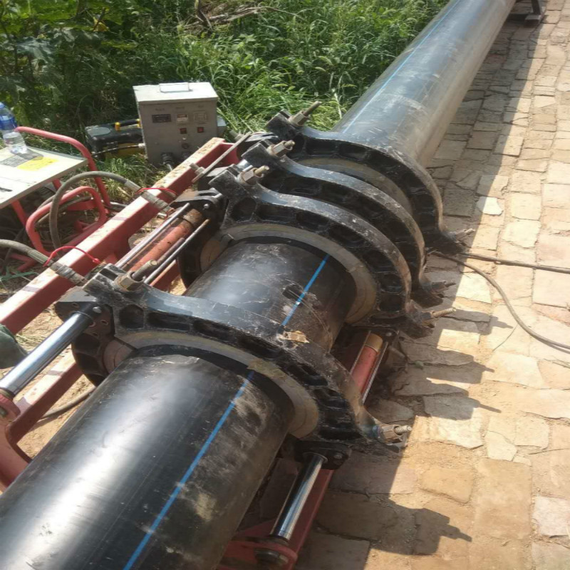
n Reliable connection performance: HDPE pipe hot melt or fused interface strength is higher than the pipe body, the seam will not be disconnected due to the soil movement or the load effect;
n Good construction performance: light pipe, welding process is simple, easy construction, the comprehensive cost of the project is low.


HDPE Water Supply Pipes
Hdpe Water Supply Pipes,Hdpe Water Supply Plastic Pipe ,Hdpe Pipe For Water Supply,Black Water Supply Hdpe Pipes
Hebei Fangyu Trade Co., Ltd. , https://www.filtersmaterial.com