InterBus Fieldbus Control System Online Fault Diagnosis
The InterBus fieldbus is one of the IEC61158 standards and is widely used in the manufacturing and machine processing industries. The material call control system in the automobile production process adopts InterBus fieldbus technology to reconstruct the production logistics on the existing production line, and realizes the demand for synchronized logistics of the enterprise.
I. INTRODUCTION The InterBus fieldbus, as one of the IEC61158 standards, is an open type serial bus system. Its data transmission speed is fast and the efficiency is high. Bus controllers and bus devices have intelligent and strong fault diagnosis capabilities. Used in manufacturing and machine processing industries. The material call control system in the automobile production process adopts InterBus fieldbus technology to reconstruct the production logistics on the existing production line, and realizes the demand for synchronized logistics of the enterprise. The system enables timely and efficient material supply, saves space on the side of the material line, reduces line-side inventory and storage inventories, automatically counts missing materials, time, and frequency, effectively preventing unnecessary delays, waiting time, and material The shortage created a problem of stopping the line. The control system has an on-line fault diagnosis function, which reduces the time for system troubleshooting and improves the reliability of the system operation and the factory production efficiency.
Second, the control system composition Material call control system consists of hardware and software components. The hardware mainly consists of IPC, fieldbus controller, bus coupler BK module, digital input and output module DIO, SAB module, LED display screen, light box and buttons. The field bus controller uses RFC430, which has functions such as data acquisition, logic control, information exchange and automatic diagnosis. The control system software consists of a control program and a fault diagnosis program.
The control program functions as follows: According to the automobile production requirements, when the production line side inventory is below the minimum value, the production worker presses the corresponding button on the station, the bus controller according to the process data sent back, through a communication based on the InterBus fieldbus The module sends the name of the material, the number of the station number, and other information to the LED large-screen display, and at the same time starts the music ringtone and the light corresponding to the material on the light box. After the warehouse staff gets the information, press the corresponding button below the light of the light box to indicate that the information is confirmed and the feed has been started. The bus controller according to the confirmation information, the indicator above the station button from the bright light to a bright state, indicating that the material is being sent. When the logistics reaches the calling station, the operator resumes the button and the material distribution process ends. The material's name, calling station, call time, place time, feeders and other information are recorded in the database of the upper computer as an indicator for managers to assess employees.
Diagnostic programs include diagnostics and self-startup programs running on the controller and OPC (OLEForProcessControl) applications running on the host computer (IPC). Once the control system fails, the bus stops operating. The online fault diagnosis program can quickly diagnose the cause of the fault, and use OPC technology to transmit the diagnostic information of the RFC430 bus controller to the host computer. The host computer uses the expert database technology to provide more detailed fault management for the management personnel based on the diagnostic information transmitted by the controller. Causes and treatment methods. Therefore, once the control system fails, the on-duty personnel can quickly eliminate the fault according to the fault diagnosis information and the processing method. After troubleshooting, the system can automatically start the bus and resume normal operation.
III. DIAGNOSIS AND AUTO-INITIATION PROCEDURE The standard registers in the InterBus bus controller RF430 provide status information of the bus operation and can also operate the bus system through the control program. The standard registers in the bus controller include diagnostic status registers, diagnostic parameter registers, standard function enable registers, standard function status registers, and standard function parameter registers. The address of the register can be set in the input or output address area of ​​the control system using PCWORX configuration software for application in programming. The diagnostic status register is one word long and each bit reflects some aspect of the bus system's operational status. The diagnostic parameter register provides more detailed information for the status bits of the diagnostic status register. The diagnostics parameter register provides the error position when a peripheral device fails or the bus error occurs. The diagnostics parameter register provides an error code when the controller and bus are faulty.
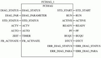
The diagnostics and self-startup programs were developed on the ProgramWorx functional programming software in PCWORX2.02. They were programmed in the ST (Structured Text) language and programmed into the functional module FCDIAG (see Figure 1). The module takes the diagnostic status register and diagnostic parameter register as input, and after processing, assigns diagnostic information to the global external variables ERRDIAGSTATUS and ERRDIAG_PAPA. The self-start function can detect whether the fault is cleared or not. Once the fault has been cleared, start the bus through the standard function start register.
IV. Application 1.OPC Data Access Object linking and embedding technology in OPC process control. OPC bases on component object model and distributed component object model technology. It adopts the client/server model to define a group of COM objects and their interfaces. The standard is an interface standard between the industrial control and production automation fields for connecting data sources (OPC servers) and data consumers (OPC applications).
The OPC data access methods mainly include synchronous access, asynchronous access, and subscription data acquisition. For asynchronous access, the OPC server receives the OPC application's requirements and returns the method almost immediately. The OPC application does not have to wait and can handle other tasks. When the OPC server completes the data access, it triggers the asynchronous access completion event of the OPC application program. The OPC application program accepts the data transmitted from the OPC server in the VB event processing program. For the subscription mode data collection, the OPC server also triggers the event. Transfer data to OPC application.
2. Diagnostic part of the OPC application developed using Visual Basic (1) The variable declaration includes the OPCServer object, the OPCGroups object, the OPCGruop object, the OPCItems object, and an array of server handles that hold the OPC tags SeverHandles_Bus(). The statement is as follows:
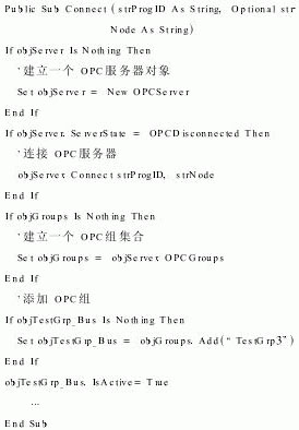
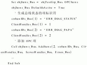
(2) connect to the server and create a group (3) Add tags
(4) Adopting the data acquisition mode of the subscription acquisition mode, the OPC application program does not need to issue a read request. When the OPC server detects that there is a change in data, it automatically notifies and transmits the changed data to the OPC application program through the event objTestGrp_BusDataChange. Based on the error information transmitted, the VB application program obtains a more detailed explanation of the cause of the fault and its processing method by querying the database. The processing method in the database is composed of expert experience and knowledge and can be continuously updated and enriched.
V. Concluding remarks Since the material call control system in the automobile production process has been put into operation since 2003, it has performed well and reached the expected control requirements. The system's implementation of the company's logistics management has reached a stage and has achieved good economic benefits. The on-line fault diagnosis function in the control system improves the reliability of the system operation, which can greatly reduce the system's fault processing time and is conducive to give full play to the system's superiority.
I. INTRODUCTION The InterBus fieldbus, as one of the IEC61158 standards, is an open type serial bus system. Its data transmission speed is fast and the efficiency is high. Bus controllers and bus devices have intelligent and strong fault diagnosis capabilities. Used in manufacturing and machine processing industries. The material call control system in the automobile production process adopts InterBus fieldbus technology to reconstruct the production logistics on the existing production line, and realizes the demand for synchronized logistics of the enterprise. The system enables timely and efficient material supply, saves space on the side of the material line, reduces line-side inventory and storage inventories, automatically counts missing materials, time, and frequency, effectively preventing unnecessary delays, waiting time, and material The shortage created a problem of stopping the line. The control system has an on-line fault diagnosis function, which reduces the time for system troubleshooting and improves the reliability of the system operation and the factory production efficiency.
Second, the control system composition Material call control system consists of hardware and software components. The hardware mainly consists of IPC, fieldbus controller, bus coupler BK module, digital input and output module DIO, SAB module, LED display screen, light box and buttons. The field bus controller uses RFC430, which has functions such as data acquisition, logic control, information exchange and automatic diagnosis. The control system software consists of a control program and a fault diagnosis program.
The control program functions as follows: According to the automobile production requirements, when the production line side inventory is below the minimum value, the production worker presses the corresponding button on the station, the bus controller according to the process data sent back, through a communication based on the InterBus fieldbus The module sends the name of the material, the number of the station number, and other information to the LED large-screen display, and at the same time starts the music ringtone and the light corresponding to the material on the light box. After the warehouse staff gets the information, press the corresponding button below the light of the light box to indicate that the information is confirmed and the feed has been started. The bus controller according to the confirmation information, the indicator above the station button from the bright light to a bright state, indicating that the material is being sent. When the logistics reaches the calling station, the operator resumes the button and the material distribution process ends. The material's name, calling station, call time, place time, feeders and other information are recorded in the database of the upper computer as an indicator for managers to assess employees.
Diagnostic programs include diagnostics and self-startup programs running on the controller and OPC (OLEForProcessControl) applications running on the host computer (IPC). Once the control system fails, the bus stops operating. The online fault diagnosis program can quickly diagnose the cause of the fault, and use OPC technology to transmit the diagnostic information of the RFC430 bus controller to the host computer. The host computer uses the expert database technology to provide more detailed fault management for the management personnel based on the diagnostic information transmitted by the controller. Causes and treatment methods. Therefore, once the control system fails, the on-duty personnel can quickly eliminate the fault according to the fault diagnosis information and the processing method. After troubleshooting, the system can automatically start the bus and resume normal operation.
III. DIAGNOSIS AND AUTO-INITIATION PROCEDURE The standard registers in the InterBus bus controller RF430 provide status information of the bus operation and can also operate the bus system through the control program. The standard registers in the bus controller include diagnostic status registers, diagnostic parameter registers, standard function enable registers, standard function status registers, and standard function parameter registers. The address of the register can be set in the input or output address area of ​​the control system using PCWORX configuration software for application in programming. The diagnostic status register is one word long and each bit reflects some aspect of the bus system's operational status. The diagnostic parameter register provides more detailed information for the status bits of the diagnostic status register. The diagnostics parameter register provides the error position when a peripheral device fails or the bus error occurs. The diagnostics parameter register provides an error code when the controller and bus are faulty.
The diagnostics and self-startup programs were developed on the ProgramWorx functional programming software in PCWORX2.02. They were programmed in the ST (Structured Text) language and programmed into the functional module FCDIAG (see Figure 1). The module takes the diagnostic status register and diagnostic parameter register as input, and after processing, assigns diagnostic information to the global external variables ERRDIAGSTATUS and ERRDIAG_PAPA. The self-start function can detect whether the fault is cleared or not. Once the fault has been cleared, start the bus through the standard function start register.

Figure 1 Diagnostic and self-starting modules
IV. Application 1.OPC Data Access Object linking and embedding technology in OPC process control. OPC bases on component object model and distributed component object model technology. It adopts the client/server model to define a group of COM objects and their interfaces. The standard is an interface standard between the industrial control and production automation fields for connecting data sources (OPC servers) and data consumers (OPC applications).
The OPC data access methods mainly include synchronous access, asynchronous access, and subscription data acquisition. For asynchronous access, the OPC server receives the OPC application's requirements and returns the method almost immediately. The OPC application does not have to wait and can handle other tasks. When the OPC server completes the data access, it triggers the asynchronous access completion event of the OPC application program. The OPC application program accepts the data transmitted from the OPC server in the VB event processing program. For the subscription mode data collection, the OPC server also triggers the event. Transfer data to OPC application.
2. Diagnostic part of the OPC application developed using Visual Basic (1) The variable declaration includes the OPCServer object, the OPCGroups object, the OPCGruop object, the OPCItems object, and an array of server handles that hold the OPC tags SeverHandles_Bus(). The statement is as follows:

(2) connect to the server and create a group


(4) Adopting the data acquisition mode of the subscription acquisition mode, the OPC application program does not need to issue a read request. When the OPC server detects that there is a change in data, it automatically notifies and transmits the changed data to the OPC application program through the event objTestGrp_BusDataChange. Based on the error information transmitted, the VB application program obtains a more detailed explanation of the cause of the fault and its processing method by querying the database. The processing method in the database is composed of expert experience and knowledge and can be continuously updated and enriched.
V. Concluding remarks Since the material call control system in the automobile production process has been put into operation since 2003, it has performed well and reached the expected control requirements. The system's implementation of the company's logistics management has reached a stage and has achieved good economic benefits. The on-line fault diagnosis function in the control system improves the reliability of the system operation, which can greatly reduce the system's fault processing time and is conducive to give full play to the system's superiority.
Special Injection Molding Machine Series
Pvc Injection Machine,Injection Molding Machine For Hanger,Mobile Phone Case Injection Molding Machine,Helmet Injection Molding Machine
Ningbo Outai Plastic Machinery Technology Co.,Ltd , https://www.outacmachine.com