Numerical Control Transformation and Design of 4R Crankshaft Grinder
Coordinate ring control. The Z-axis motor is made of a single-axis amplifier SVU1 X-axis with no bumper block. The Y-axis and the Z-axis respectively establish points by means of a collision block. Since the X and Y axes use an absolute position encoder, once the point is established, there is no need to return to zero as long as it is not lost. The Z-axis uses an incremental scale, and each time the machine is restarted, or the zero point is lost, it needs to be reset to zero to establish a point.
Third, the coordinate axis flexible feed transmission ratio retains the original mechanical drive train for both the X-axis and the Y-axis. The specific method is as follows: firstly, the screw pitch is 10mm and the transmission ratio is 1:1. The actual transmission ratio is determined by comparing the amount of movement of the coordinate axis with the amount of movement of the system display. Further, it is possible to calculate the stroke feed amount generated by one revolution of the motor. The stepping motor is used for the original X-axis and Y-axis of the machine tool, so the deceleration of the configuration is relatively large. Through the actual measurement, the X-axis motor is fed into the 400mm Y-axis motor. The one-turn feed 1250mmX and the Y-axis are semi-closed loop control, and the flexible feed transmission ratio is calculated according to formula (1).
Feed the shaft for the grinding wheel. The Z axis is the table axis. The Y axis is the dresser axis. Since 0GCC is a single channel controller to improve the beat, the X and Z axes are defined as the numerical control rail Y axis is defined as the PMC axis.
All of the dresser controls are included in the PMC control area, and all operations of the dresser are controlled by the PMC program for independent parallel operation of grinding and dressing.
/O configuration ffg motor required position feedback pulse number G1000000 general-purpose inverter one-headstock motor is set, the system appears 417 and 447 alarm, indicating that the position gain has overflowed. In this case, you need to specify the position gain range extension function. The specific settings are as follows: 1. Parameter No. 8X115 is set to 1, and the position gain range expansion function is enabled.
2 The flexible feed ratio and the command multiplication ratio CMR are multiplied by 8X and the Y-axis flexible transmission ratio are 2/625 and 1/100, respectively. CMR is the same. 3. In-situ width, position error limit, reverse The parameters such as the limit are multiplied by 8 and then set.
For the Z axis, the grating ruler is used for position feedback to form a full closed loop control. The flexible transmission ratio of (2) the electric position of the grinding wheel must be more than 15 mm backward relative to the previous grinding size. (3) During the advancement of the grinding wheel, if the load is too large, the grinding wheel will be returned.
Due to grinding wheel dressing and grinding wheel wear, the diameter of the grinding wheel is decreasing.
Therefore, the X axis must be compensated for each ablation. The compensation principle is: each time the size is milled, the current X-axis mechanical coordinate value (525= 5021) is memorized and then the position working coordinate is set to 0 (G50X0). In order to ensure that the system is powered off after power failure, or other abnormal operation, the X-axis With the correct coordinate system, the coordinate system must be set for the X axis at the beginning of the grinding. The program instructions are as follows: At the same time, in order to prevent the X-axis coordinate system setting error, coordinate system verification is also designed. The verification principle is: the machine coordinate 5021 minus the workpiece coordinate 5041 must be equal to 525, otherwise a 502 alarm is generated.
The two 4R crankshaft spindle grinding machines were successively transformed. After the transformation, the expected process processing requirements were fully achieved, and the system was stable and reliable. This shows that the universal cylindrical grinding CNC system is specifically designed for the control of crankshaft grinding machines.
No. 28, Checheng West Road, City, 442002 [Editing Wu Siming] Technical transformation equipment management and maintenance 2004Nq1 27
(Finish)
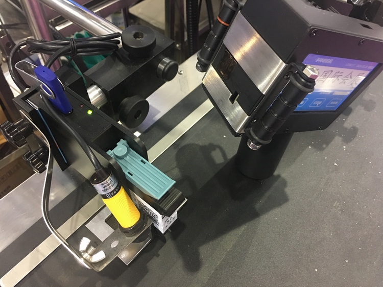
The HAE TIJ printer offers an idea solution to move from messy low resolution Drop On Demand (DOD), Roller Coders or expensive to operate and service continuous inkjet marking printer (CIJ) to a high quality, high resolution HAE Thermal Ink Jet Printer (TIJ) using the latest original HP ink cartridges for reliable print onto primary and secondary packaging. A compact, low cost solution for Lot Codes, Date and Time, Sell by and Best Before and Use-By Dates, Product Information, Batch and Production data, Traceability Codes, Specifications, Branding, Sequential numbers, Expiry dates, bar codes, logo and free text to meet your coding needs. Simple to use and PC software included with the HAE Inkjet marker makes complex messages easy to manage and to easily back up or move to other HAE TIJ coding printers for security of code.

Tij Inkjet Printer,TIJ Inkjet Coder,Thermal Inkjet Printer,Date Coding Machine,Inkjet Marking Machine,Inkjet Marking Printer,Thermal Inkjet Printer
Wuhan HAE Technology Co., Ltd. , https://www.whuvwallprinter.com