The use and maintenance of vortex flowmeter
1 How vortex flowmeters work
Vortex flowmeter is a speed flowmeter, which is composed of transmitter and signal converter composed of vortex generator and frequency detector. The measurement principle is that in a flowing fluid, if a vortex generator is placed in the direction of vertical flow, within a range of Reynolds numbers, a regular vortex will alternately appear on both sides of the vortex generator (see Figure 1). The vortex arrays are arranged asymmetrically downstream of the vortex generators.

Figure 1 Vortex generators and vortices
Let the vortex frequency be f, the average velocity of the medium to be measured be v, the width of the vortex body to face be d, and the frequency f between the unilateral vortex and the velocity v and d have the following relationship.

In the formula, Sr is a function of Reynolds number. In the range of ReD=2×10 4 to 7×10 6, Sr can be regarded as a constant, and the vortex street frequency is proportional to the volumetric flow rate.
Vortex flowmeters can measure the flow of liquids, gases, and vapors in a single state. In the case of miscible fluids, the flowmeter cannot make accurate measurements. Vortex flowmeters have an integral type and a split type.
2 Vortex Flowmeter Installation
Vortex flowmeter sensor is divided into flange type, clamp type, plug-in type. Flange type is preferred for the type selection, followed by the clamp type, and the insert type is not considered. The reason is that the accuracy of the clamped and plug-in flowmeters is greatly affected by the installation. Unqualified installations will cause a large measurement error.
The vortex flowmeter must be installed with the arrow on the sensor nameplate pointing in line with the fluid flow direction and the minimum straight-ahead pipe section requirements in the figure below must be satisfied. At the same time to comply with the following requirements.
2.1 Measurement of Gas or Steam Meter Installation
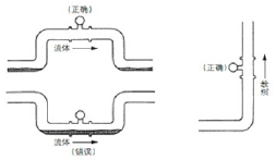
When measuring gas or steam, the vortex flowmeter is installed on a horizontal pipeline. When piping, care should be taken to prevent liquid stagnation. The vortex flowmeter should be installed at a higher point of the pipeline or the pipe section with the vortex flowmeter installed should be elevated. The vortex flowmeter is installed on the vertical pipe, and the flow direction is not limited. If the measured gas contains a small amount of liquid, the gas flow should be downward, as shown in Figure 2.

Figure 2 Installation of measuring gas or steam vortex flowmeter
2.2 Measuring Liquid Flow Meter Installation
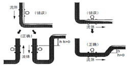
To ensure accurate measurements when measuring liquids, the vortex flowmeter's piping must be filled with liquid. When the vortex flowmeter is installed on a horizontal pipeline, the downstream segment of the pipeline should be higher than the vortex flowmeter to maintain full flow; when the fluid flows downward, the downstream segment of the pipeline should be higher than the vortex flowmeter. Stay full. When the flowmeter is installed on a vertical pipe, the fluid should flow upward. When the fluid flows downward, the pipe in the downstream section should be higher than the vortex flowmeter to maintain the full pipe, as shown in Figure 3.

Figure 3 Installation of a liquid vortex flowmeter
2.3 Flowmeter and control valve position relationship
The control valve should be installed downstream of the vortex flowmeter. This can solve the negative effect of the bubble due to the pressure drop when the liquid flows through the control valve. See Figure 4. When the vortex flowmeter is installed in a horizontal pipeline, when the temperature of the measured medium is greater than 200°C, the transmitter must be installed downward.

Figure 4 Vortex flowmeter and control valve position
Spark Plug Wires, Iridium Spark Plugs,F6Rtc Spark Plug,Engine Spare Parts Double Iridium Spark Plug
1D auto parts , https://www.1dauto.com