Principle and Application of Subdivision Control of Meter Stepper Motor Based on ATMEGA48 Microcontroller
Stepper motors are open-loop control elements that convert electrical pulse signals to angular or linear displacements. In the case of non-overload, the motor speed and stop position depend only on the frequency and pulse number of the pulse signal, and is not affected by the load change. That is, a pulse signal is added to a phase coil of the motor, and the motor rotates a step. angle. The existence of this linear relationship, combined with the fact that the stepper motor has only periodic errors and no accumulated errors, makes it easy to control with a stepper motor in speed, position, and other control areas. Although stepper motors have been widely used, stepper motors are not conventionally used as ordinary DC motors and AC motors. It must be used under a control system consisting of a double ring pulse signal and a power drive circuit.
Instrument stepper motors belong to the class of stepper motors in terms of volume and power consumption. They can be directly driven by the pins of a single-chip microcomputer or a dedicated chip, and do not require an external driver. Therefore, they are used for the rotation control of pointers in meters.
Demand analysis The instrument used in this scenario has the following characteristics and design parameters:
â— The pointer responds sensitively and accurately. It means that the driver can't lose the step after receiving the driving pulse.
â— The pointer rotates steadily, that is, the position of the pointer from the current position to the target position must be stable, and both the positive and negative directions cannot be shaken.
â— Two-phase, step angle 10o, rotation range 300o.
According to the technical parameters, the step angles of two-phase four-shot and two-phase eight-shot are 10o and 5o. Within the range of 300o, only 30 and 60 scales can be divided. In practical applications, pointer steps are found. The corners do not meet the requirements and jitter is unavoidable. In order to accurately position and operate the pointer with high precision, it is necessary to perform high-resolution subdivision on the stepping distance of the stepping motor, which is also a difficulty in design.
Stepping motor subdivision technology is an electronic damping technology, its main purpose is to improve the motor's running accuracy, stepper motor to achieve high precision subdivision step angle. The basic concept is: stepper motor drive through the subdivision driver, its step angle becomes smaller. If the driver works in the 10 subdivision state, its step angle is only one-tenth of the motor's inherent step angle. Take two-phase four-shot as an example: When the motor works in the undivided full-step state, the control system sends a stepping pulse for each step, the motor rotates 10o; when the subdivision driver works in the 10 subdivision state, the motor rotates only 1o. The subdivision function is completely realized by the driver or the microcontroller by precisely controlling the phase current of the motor, and has nothing to do with the motor itself.
Subdivision principle The two-phase four-shot A, B, /A, /B drive state table is shown in Table 1.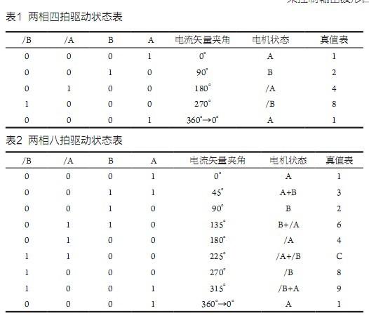
From the above analysis, it can be seen that the two-phase four-shot is not subdivided in the whole-step operation, and the two-phase eight-shot is actually two subdivisions. The combined magnetic field and current vector angles change between 90o and 45o, and so on and around.
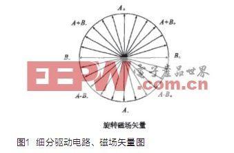
After referring to relevant data, it is not difficult to find that subdivided drive technology often uses a step-like current similar to a sine wave instead of a rectangular wave current to generate a micro-step rotating magnetic field, thereby driving the motor to rotate at a smaller step angle, its current waveform and rotating magnetic field The vector is shown in Figure 1. At the same time, the sinusoidal current changes smoothly, making the motor run more smoothly and with less noise. That is, by changing the magnitude and direction of the currents (A, B) of the adjacent two phases (A-phase sine wave and B-phase cosine wave vector superposition) to change the angle of the combined magnetic field, the stepping motor is controlled by the current vector synthesis method. Operation.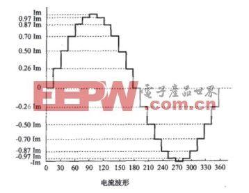
According to the principle of subdivision, we can see that for a two-phase stepper motor, the voltage magnitude and direction of the two coils need to be controlled at the same time to achieve the purpose of synthesizing the current vector control. There are two schemes for controlling the current of the coil: one is written by the microcontroller. Digital quantity, the analog-digital conversion device outputs the analog voltage, control coil current size; The second is through some microcontroller's own PWM pin output controllable square wave, with its AC RMS control coil current size. Obviously, the duty cycle that changes according to sine law decides that the coil current size also changes according to the same sine law. The voltage application direction of the coil can be realized by a logic gate circuit.
In summary, the ATMEGA48 single-chip microcomputer with two 16-bit precision PWM functions is selected, and the peripheral hardware circuit design is shown in FIG. 2 .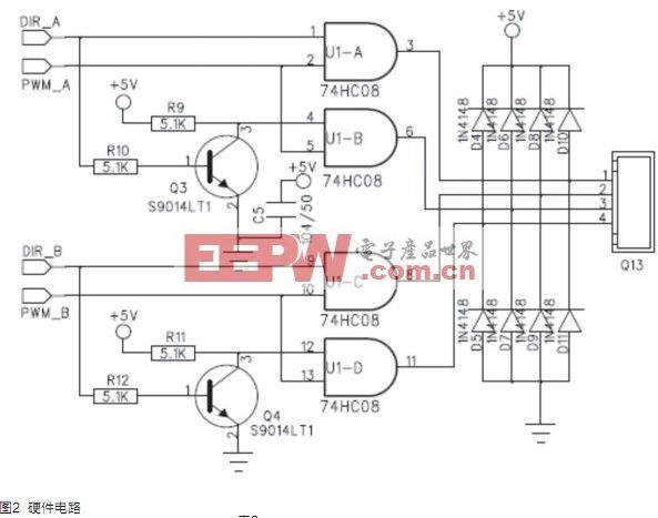
Use the one-chip computer PWM function PB1 and PB2 to connect PWM_A and PWM_B, use two ordinary pins to connect DIR_A and DIR_B to realize the control to the electrical machinery. The principle is described as follows: A, /A, B, /B of the motor correspond to the 3, 6, 8, and 11 pins of the four-input AND gate circuit. When DIR_A and DIR_B are at a low level, the 1 and 9 pins of the gate circuit are in the 0 state, and the transistors Q3 and Q4 are turned off. The 4 and 12 pins of the gate circuit are in a state of 1 because of the pull-up. Thus, the AND gate circuit 3 and 3. 8 The output is 0, that is, A, B is 0; At this moment, the output of the AND circuit 6 and 11 are consistent with PWM_A and PWM_B, ie /A, /B are determined by PWM_A and PWM_B. In other states, it also has the same characteristics: the polarity of the energization between A and /A, between B and /B is determined by DIR_A and DIR_B; the current between A and /A, and between B and /B is determined by The duty cycle of PWM_A and PWM_B is determined. And as long as the transistors Q3, Q4 work properly, the AND gate circuit will not appear logical confusion.
With the design of the hardware, an array of 64 data was written on the software, corresponding to the 8-bit digital quantizing value of the 0-90o sine wave amplitude change (64-sine wave sampling was simulated in a staircase wave manner). The values ​​are used to control the duty cycle of the output waveform and actually participate in the calculation of the current magnitude during the 90° rotation of the current vector angle. As we all know, the sine and cosine waves are 90o out of phase. After the 0~90o sine wave amplitude change table is known, the 90o~180o, 180o~270o, 270o~360o(0o) sine wave and cosine wave amplitude change tables can also be obtained. Therefore, through the evolution of an 8-bit digital quantization table whose amplitude changes from 0 to 90o sine wave, the current vector angle can be divided into four quadrants based on two phases of eight beats (two subdivisions), with the control of polarity. In each quadrant, 8 sine waves of A or /A and cosine waves of B or /B are used to complete the change of current magnitude in each combination, and finally make two phases of 64 beats (16 subdivisions). control. Moreover, the most ingenious point is that by selecting 64 data points corresponding to 64 points of a sine wave of every 90o range, one byte size can be used as a mark for distinguishing the four quadrants, so that the angles of the positive and cosine angles can be easily determined. For evolution, 0~63 corresponds to 0~90o, 64~127 corresponds to 90o~180o, 128~191 corresponds to 180o~270o, and 192~255 corresponds to 270o~360o.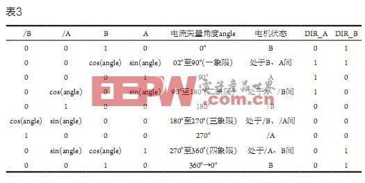
Since the meter pointer points from the current angle to the target angle, the amount of change will be different. In order to ensure that the pointer responds sensitively and without jitter, acceleration and deceleration control must be considered in the positive and negative directions. In the program, several control intervals can be set according to the magnitude and the positive and negative values ​​of the variation, and different delay parameters can be written respectively. According to this delay parameter, the current size and direction (changing PWM_A, PWM_B, DIR_A, and DIR_B) can be controlled. Time, to achieve the purpose of control of acceleration and deceleration.
Conclusion The control of two-phase stepper motors through dual PWM methods achieves both high-precision subdivision and hardware optimization. The addition of a power driver circuit at the later stage of the existing circuit and a minor modification of the program can result in a high-precision, multi-subdivision stepper motor driver.
Instrument stepper motors belong to the class of stepper motors in terms of volume and power consumption. They can be directly driven by the pins of a single-chip microcomputer or a dedicated chip, and do not require an external driver. Therefore, they are used for the rotation control of pointers in meters.
Demand analysis The instrument used in this scenario has the following characteristics and design parameters:
â— The pointer responds sensitively and accurately. It means that the driver can't lose the step after receiving the driving pulse.
â— The pointer rotates steadily, that is, the position of the pointer from the current position to the target position must be stable, and both the positive and negative directions cannot be shaken.
â— Two-phase, step angle 10o, rotation range 300o.
According to the technical parameters, the step angles of two-phase four-shot and two-phase eight-shot are 10o and 5o. Within the range of 300o, only 30 and 60 scales can be divided. In practical applications, pointer steps are found. The corners do not meet the requirements and jitter is unavoidable. In order to accurately position and operate the pointer with high precision, it is necessary to perform high-resolution subdivision on the stepping distance of the stepping motor, which is also a difficulty in design.
Stepping motor subdivision technology is an electronic damping technology, its main purpose is to improve the motor's running accuracy, stepper motor to achieve high precision subdivision step angle. The basic concept is: stepper motor drive through the subdivision driver, its step angle becomes smaller. If the driver works in the 10 subdivision state, its step angle is only one-tenth of the motor's inherent step angle. Take two-phase four-shot as an example: When the motor works in the undivided full-step state, the control system sends a stepping pulse for each step, the motor rotates 10o; when the subdivision driver works in the 10 subdivision state, the motor rotates only 1o. The subdivision function is completely realized by the driver or the microcontroller by precisely controlling the phase current of the motor, and has nothing to do with the motor itself.
Subdivision principle The two-phase four-shot A, B, /A, /B drive state table is shown in Table 1.

The two-phase eight-shot A, B, /A, /B drive state table is shown in Table 2.
From the above analysis, it can be seen that the two-phase four-shot is not subdivided in the whole-step operation, and the two-phase eight-shot is actually two subdivisions. The combined magnetic field and current vector angles change between 90o and 45o, and so on and around.
After referring to relevant data, it is not difficult to find that subdivided drive technology often uses a step-like current similar to a sine wave instead of a rectangular wave current to generate a micro-step rotating magnetic field, thereby driving the motor to rotate at a smaller step angle, its current waveform and rotating magnetic field The vector is shown in Figure 1. At the same time, the sinusoidal current changes smoothly, making the motor run more smoothly and with less noise. That is, by changing the magnitude and direction of the currents (A, B) of the adjacent two phases (A-phase sine wave and B-phase cosine wave vector superposition) to change the angle of the combined magnetic field, the stepping motor is controlled by the current vector synthesis method. Operation.


Hardware Design and Software Programming
According to the principle of subdivision, we can see that for a two-phase stepper motor, the voltage magnitude and direction of the two coils need to be controlled at the same time to achieve the purpose of synthesizing the current vector control. There are two schemes for controlling the current of the coil: one is written by the microcontroller. Digital quantity, the analog-digital conversion device outputs the analog voltage, control coil current size; The second is through some microcontroller's own PWM pin output controllable square wave, with its AC RMS control coil current size. Obviously, the duty cycle that changes according to sine law decides that the coil current size also changes according to the same sine law. The voltage application direction of the coil can be realized by a logic gate circuit.
In summary, the ATMEGA48 single-chip microcomputer with two 16-bit precision PWM functions is selected, and the peripheral hardware circuit design is shown in FIG. 2 .

Use the one-chip computer PWM function PB1 and PB2 to connect PWM_A and PWM_B, use two ordinary pins to connect DIR_A and DIR_B to realize the control to the electrical machinery. The principle is described as follows: A, /A, B, /B of the motor correspond to the 3, 6, 8, and 11 pins of the four-input AND gate circuit. When DIR_A and DIR_B are at a low level, the 1 and 9 pins of the gate circuit are in the 0 state, and the transistors Q3 and Q4 are turned off. The 4 and 12 pins of the gate circuit are in a state of 1 because of the pull-up. Thus, the AND gate circuit 3 and 3. 8 The output is 0, that is, A, B is 0; At this moment, the output of the AND circuit 6 and 11 are consistent with PWM_A and PWM_B, ie /A, /B are determined by PWM_A and PWM_B. In other states, it also has the same characteristics: the polarity of the energization between A and /A, between B and /B is determined by DIR_A and DIR_B; the current between A and /A, and between B and /B is determined by The duty cycle of PWM_A and PWM_B is determined. And as long as the transistors Q3, Q4 work properly, the AND gate circuit will not appear logical confusion.
With the design of the hardware, an array of 64 data was written on the software, corresponding to the 8-bit digital quantizing value of the 0-90o sine wave amplitude change (64-sine wave sampling was simulated in a staircase wave manner). The values ​​are used to control the duty cycle of the output waveform and actually participate in the calculation of the current magnitude during the 90° rotation of the current vector angle. As we all know, the sine and cosine waves are 90o out of phase. After the 0~90o sine wave amplitude change table is known, the 90o~180o, 180o~270o, 270o~360o(0o) sine wave and cosine wave amplitude change tables can also be obtained. Therefore, through the evolution of an 8-bit digital quantization table whose amplitude changes from 0 to 90o sine wave, the current vector angle can be divided into four quadrants based on two phases of eight beats (two subdivisions), with the control of polarity. In each quadrant, 8 sine waves of A or /A and cosine waves of B or /B are used to complete the change of current magnitude in each combination, and finally make two phases of 64 beats (16 subdivisions). control. Moreover, the most ingenious point is that by selecting 64 data points corresponding to 64 points of a sine wave of every 90o range, one byte size can be used as a mark for distinguishing the four quadrants, so that the angles of the positive and cosine angles can be easily determined. For evolution, 0~63 corresponds to 0~90o, 64~127 corresponds to 90o~180o, 128~191 corresponds to 180o~270o, and 192~255 corresponds to 270o~360o.

The two-phase 64 beat A, B, /A, /B drive state table is shown in Table 3 (starting with B).
Since the meter pointer points from the current angle to the target angle, the amount of change will be different. In order to ensure that the pointer responds sensitively and without jitter, acceleration and deceleration control must be considered in the positive and negative directions. In the program, several control intervals can be set according to the magnitude and the positive and negative values ​​of the variation, and different delay parameters can be written respectively. According to this delay parameter, the current size and direction (changing PWM_A, PWM_B, DIR_A, and DIR_B) can be controlled. Time, to achieve the purpose of control of acceleration and deceleration.
Conclusion The control of two-phase stepper motors through dual PWM methods achieves both high-precision subdivision and hardware optimization. The addition of a power driver circuit at the later stage of the existing circuit and a minor modification of the program can result in a high-precision, multi-subdivision stepper motor driver.
Metallic Filter,Wire Mesh Filter,Sintered Bronze Filter,Sintered Filters
Anping Guangtong Hardware Wire Mesh Co.,Ltd , https://www.gthardwaremesh.com